Key Takeaways
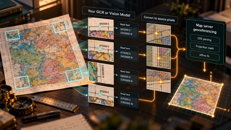
- The task today: Georeferencing a scanned geologic map starts from its control points: in a desktop GIS an analyst clicks each tick, which is measuring, and types the coordinate printed beside it, which is reading. Stratigraphic Amenity, an open-source server whose tools an AI agent calls to georeference maps and look up geology (an MCP server), leaves the reading to your own OCR or vision model on purpose and keeps the CRS parsing and projection math.
- The problem: The measuring half of every control point lands on the caller’s side too, and a vision model asked for positions reports them in the frame of the picture it saw (a downsampled preview, a crop). The fit absorbs an error that every point shares: in a worked example on a hypothetical scan, such positions gave near-zero residual and leave-one-out holdout error (the largest miss when each point is predicted from a fit to the others), while the map’s box moved by hundreds of metres to tens of kilometres.
- What the tool does:
geomap_georeferencetakes each control point as four plain numbers and, by default, pairs them with the server’s own map area, the detected main-map box in full-resolution source pixels, so it cannot tell which frame your pixels came from. Let the model read and let code measure: cut windows from the source image, convert each position the model reports to that window’s own pixels, add the window’s offset, and check that every tick sits near an edge of the main-map box.
TL;DR
Pairing your own OCR or vision model with a geologic map server? Stratigraphic Amenity, an open-source server whose tools AI agents call (an MCP server), leaves the reading of tick labels, the CRS note and legend text to your model, but every ground control point also needs a pixel position, and that measurement lands on your side too. A vision model reports positions in the frame of the image it saw, and the fit cannot see a frame error that every point shares, so let the model read, let code convert each position into full-resolution source pixels, and check each tick against the server’s main-map box.
What Does a Geological AI Server Leave to Your Model?
A geological AI agent working from a scan starts by reading it. Hand a vision model the corner of a scanned geologic map and ask what is printed there. It will tell you that one tick label reads 660000 E and another 5400000 N. That is the part of the job everyone worries about. It is also the part a map server can fairly assume a model will do.
The harder question is the one the model is rarely asked: where, in pixels, is that tick?
Stratigraphic Amenity, our open-source MCP server for scanned geologic maps, leaves the reading to you on purpose. Its README lists what the package does not include: OCR, a vision-language model, automatic GCP extraction, remote MCP transport and final answer generation. The agent guide says it in one line: the server “does not read text, decide which evidence is true, or produce the final answer.” What it keeps is the work that should never be guessed. The docstring at the top of its georeferencing module draws the line plainly: “The agent supplies the GCPs (reading printed tick labels is its strength); this module owns the projection math.”
The Line Runs Through the Control Point
It is a sensible split, and it is not where the errors live. A ground control point is four numbers. Two of them, world_x and world_y, come off a printed label. The other two, pixel_x and pixel_y, are a measurement. Anyone who has georeferenced a scan in a desktop GIS knows the difference with their hands. You click the tick, which is measuring, and type the coordinate, which is reading. The server’s boundary between “the model reads” and “the package computes” runs through the middle of every control point. The measuring half lands on the caller’s side.
The Legend Is Measured, the Ticks Are Not
The package knows how to split those jobs when it chooses to. For the legend it does the measuring itself. The layout and legend detector finds each colour swatch and the text box beside it, and pairs them. It then returns the text box in full-resolution source pixels. As a result, an OCR step only has to read a crop whose position is already known.
For the coordinate ticks it stops short. It cuts the four corners of the main map, each a tenth of its width and height. Then it stitches them into one 2 by 2 picture for a model to read. That picture is good for reading and no help for measuring. The server registers it with no bounding box, so nothing in the payload records where its pixels sit on the source.
Every Picture a Vision Model Sees Has Its Own Frame
A vision model reports positions in the frame of the image it was given, and a typical agent juggles several. The server’s structured payload is in the source frame. The server downsamples the image it attaches inline to a 1,536-pixel long edge or less and labels it coordinate_frame: "preview". Its text summary tells the model not to measure on it. Similarly, every crop starts at its own (0, 0). The corner mosaic stitches four distant regions edge to edge. And the model brings its own convention. Some models report positions on a 0 to 1,000 grid. Others report pixels of the resized image they actually received. In addition, many vision APIs resize large images before the model sees them.
Get the frame wrong and you might expect the georeference to complain. It doesn’t, and the reason is instructive. An affine transform absorbs any scale or shift that every point shares. If every tick position is off by the same factor, the points still agree with each other perfectly. Agreement is all that the residuals and the leave-one-out holdout error can measure.
How a Frame Error Slips Past a Geological AI Fit
We checked this with the package’s own fitting function on a hypothetical 6,000 by 4,500 pixel scan at 2.5 metres per pixel. We placed one tick near each corner of the main map. As the server does by default, we took the map area from the detected main-map box:
- Positions read on the preview fitted with essentially zero residual and zero holdout error. The box landed tens of kilometres from the true one.
- Positions measured relative to the main-map crop fitted just as perfectly. They shifted the box 750 metres east and 625 metres south.
- Positions read on the corner mosaic, one tick per corner, also fitted perfectly. One edge of the box ended up about 62 kilometres out.
Only when we read two ticks in each corner did the mosaic version break, with a holdout error near 4.9 kilometres. That is because inside one corner the mosaic is a plain shift, and between corners it is not.
That is the uncomfortable consequence. With four or more points, the holdout check catches a single misread digit, because one point disagrees with the rest. A frame mistake, however, makes every point agree. A better reader does not help here: a more consistent model hands over a more consistently wrong set of positions.
Let Your Vision Model Read and Let Code Measure
So where does your model fit in a geological AI pipeline? Where the server says it does. It reads the printed coordinates, the CRS note and the legend text, and the client writes the final answer. The server parses the CRS note from an EPSG code or common UTM text such as “UTM N83 Zone 15”. It raises an error for anything else. A UTM string with no datum, or with a datum spelled outside the parser’s short list of aliases, silently becomes WGS84. Likewise, legend text goes back in as labels with each query.
The measuring should not ride along with the reading. Give positions to something that reports them in a frame you control. A classic OCR engine returns a box for every word, in the pixels of the image you passed it. Adding the crop’s own offset puts that box in the source frame. Read values on the mosaic if you like, but measure on the source image. The server exposes it as a resource of its own.
Check the Frame, Not Just the Fit
Then check the frame, not just the fit. The server returns the main-map box in source pixels. Ticks on a neatline should sit on or near its edges. For example, a tick that lands in the middle of the map, or far out in the margin, is a frame error before it is a reading error. The model is useful again here, in its strong role. Crop the source image around each reported position and ask whether a tick sits at the centre. Recognising a tick is reading. Saying where it is was never the model’s job.
The package’s refusal to read is honest, and it keeps the projection math out of the model’s hands. But the line it draws is between reading and computing, while the error budget of a georeferenced scan sits in measuring. Anyone who pairs a model with the server is building that measuring step, whether they meant to or not.
Building that step does not mean building a georeferencing stack. The projection math, the CRS parsing, the residuals and the stored revisions already exist in the open-source server. What you add is a reader, plus a few lines of code that put its positions in the right frame. Before writing those lines, find exactly where the server stops relying on its own records. That is where it starts taking your numbers as given.
That place is easy to find, because it sits in a single tool handler. The georeference tool takes your control points from one side and its own map area from the other.
Where Your Pixels Meet the Server’s Frame
The seam described above is about twenty lines at the top of the geomap_georeference handler:
    @_traced
    def georeference(
        self,
        *,
        crs: str | int,
        gcps: list[Mapping[str, Any] | list[float] | tuple[float, float, float, float]],
        pixel_extent: list[float] | tuple[float, float, float, float] | None = None,
        map_id: str | None = None,
        map_uri: str | None = None,
        main_map_artifact_uri: str | None = None,
    ) -> dict[str, Any]:
        trace_id = _active_trace_id()
        resolved_map_id = self._resolve_map_id(map_id=map_id, map_uri=map_uri, required=False)
        normalized_gcps = [_gcp_dict(gcp) for gcp in gcps]
        if pixel_extent is None and main_map_artifact_uri:
            entry = self.registry.artifact_entry(main_map_artifact_uri)
            bbox = entry.get("bbox")
            if bbox:
                pixel_extent = [float(value) for value in bbox]
        if pixel_extent is None and resolved_map_id:
            pixel_extent = self._main_map_pixel_extent(resolved_map_id)
        if pixel_extent is None:
            raise McpToolError("invalid_bounds", "pixel_extent or main map artifact bbox is required.")
Two inputs meet here, and they come from opposite sides of the line. Your control points arrive from the client, and the server only normalises them. _gcp_dict turns each one into four floats and keeps nothing else (mcp/adapter.py:1233-1247). When you don’t pass a map area, the server takes one from its own records. It uses the bounding box of a named crop, or the first detected main_map box (mcp/adapter.py:779-785). Both are in full-resolution source pixels.
Nothing between these lines asks whether your pixel numbers live in that same frame. The fit that follows (georef/transform.py:240-317) can report disagreement among your points. A set of points that all share one wrong frame gives it nothing to disagree about. That is why, in any geological AI pipeline built on this server, the frame is the caller’s responsibility. It is also why the source-frame main_map box is the cheapest check on it.
Running Geological AI Georeferencing With Your Own OCR
To try the pairing, clone the Stratigraphic Amenity repository. Install the full MCP profile, because the main-map box comes from the detector:
uv sync --group dev --extra mcp --extra geo --extra assets --extra detectorsAdd the stratigraphic-amenity-mcp command to your MCP host, with GEOMAP_MCP_ALLOWED_ROOTS set to the folder that holds your scans. The scan must sit inside an allowed root before geomap_register_map accepts it.
Call geomap_prepare_detectors once, after the user confirms the download, then geomap_register_map and geomap_process_image. Keep regions.main_map from the result, and read the full image through geomap://maps/<map-id>/source. Run your OCR or vision model on windows cut from that image. Convert each position it reports to that window’s own pixels first. A vision model may answer on a 0 to 1,000 grid, or in the pixels of a resized copy. Then add the window’s offset, and check that every tick sits near an edge of the main_map box. Finally, send the points without a pixel_extent, so the server uses its own box:
{
  "map_id": "<map-id>",
  "crs": "UTM N83 Zone 15",
  "gcps": [
    {"pixel_x": 400, "pixel_y": 400, "world_x": 601000, "world_y": 5499000},
    {"pixel_x": 5600, "pixel_y": 400, "world_x": 614000, "world_y": 5499000},
    {"pixel_x": 400, "pixel_y": 4000, "world_x": 601000, "world_y": 5490000},
    {"pixel_x": 5600, "pixel_y": 4000, "world_x": 614000, "world_y": 5490000}
  ]
}
The reply is a georef/v1 payload. It holds crs resolved to EPSG:26915, the six affine coefficients and EPSG:4326 bounds. It also holds residual_m, fit_method, gcp_pixel_errors, holdout_error, warnings and a georef_uri for the stored revision.
Legend text takes the other door. Crop each entry’s text_bbox from the source image and read it. Pass the words as legend_labels to geomap_query_map. To turn one legend label into a rock type and age, pass it as label to geomap_enrich_legend.
What to Watch For When Pairing Geological AI With OCR
The server reports some of the gaps it leaves to your model plainly, and stays silent about others. A geological AI pipeline built on it has to handle both.
What the Server Tells You
- Legend labels arrive empty.
geomap_process_imagereturns each legend entry withlabel: nullandlabel_extraction: "not_available", plus this warning: “Legend labels were not extracted; this build ships no OCR. Entries with label_extraction ’not_available’ have no transcribed text. Do not infer them from an image; ask the user or a separate OCR/VLM system.” Your model’s labels travel as call arguments, and the stored processing result keeps its blanks. - The preview is a different frame. The processing summary says: “The attached preview image is downsampled and is a different coordinate frame; do not measure coordinates on it.”
- Two or three points give the residuals nothing to check. An exact fit warns “residual_not_diagnostic: an exact fit has no independent error check; supply at least 4 well-distributed GCPs”. Only the shape checks for flipped, rotated or sheared axes remain, so a misread digit can pass along with any frame error.
What It Cannot Tell You
- A missing or unfamiliar datum is silent. Text that is neither an EPSG code nor UTM fails with “Unrecognized CRS specification”. A UTM string with no datum, or one spelled outside the parser’s short list, becomes WGS84 without a warning. For example, “NAD 1927 UTM Zone 15N” resolves to EPSG:32615, not EPSG:26715, so write the datum as “NAD27” or “NAD83”, or pass the EPSG code. Like a frame error, every point shares it, so it also passes a clean fit on coordinates alone.
- A misread label is not an absent unit. A garbled label can return “No rock type match for” that label, or a partial match flagged
match_type: "substring". An empty result from a misread label is not evidence that the unit is absent from the map. - The server forgets who read each number. It keeps four floats per control point and drops any other field. Log which model read which tick, and from which crop, yourself.
FAQs
Does the geological AI server include OCR or a vision model?
No. Stratigraphic Amenity, an open-source geological AI server, ships no OCR, vision model, automatic control point extraction or final answer generation. Its detector leaves legend labels empty. Your OCR or vision model supplies the CRS text, tick values and legend words; your code supplies each tick’s position in source pixels. The server parses the CRS, fits the georeference and runs the lookups.
How do I send OCR results to the MCP server?
Send control points to geomap_georeference as pixel_x, pixel_y, world_x and world_y, in full-resolution source pixels. Also give the CRS as an EPSG code or UTM text. Send legend words as legend_labels to geomap_query_map, or one at a time as label to geomap_enrich_legend. Finally, keep your own record of which model read each value.
Why does a geological AI fit show zero residual when the map is in the wrong place?
The residuals and the holdout error only measure how well your control points agree with each other. Positions read on a downsampled preview, or relative to a crop, all share one frame error. As a result, the affine fit absorbs it. The map’s box can then move by hundreds of metres or more without a warning.
Which coordinate frame should control point pixels use?
Use the full-resolution source image, the frame of the server’s main_map box and every detection. Scale a position reported on a crop to that crop’s own pixels, then add the crop’s offset. Read values on the preview or corner mosaic if you like, but measure on the source image. Ticks on a neatline should then sit near an edge of the main_map box.
Try It With Geocluster
Stratigraphic Amenity is one of the Geocluster tools, MCP servers that let AI agents work with geology data and maps.
Once your model’s control points pass the frame check, take them through the full open-source georeferencing pipeline.